3D asset series: - The Tower That Never Was part 1 - The Revolver
- Cade-Mason
- Jan 26, 2021
- 5 min read
Updated: Apr 2, 2021
In this blog, I will be going over my progress on 3D modelling a Revolver.
"The Tower That Never Was" assets will be a 3 blog asset series based on the assets I have modelled. The 3 assets I am going to be modelling are: - The Revolver (This blog will entail the overall process of the model.)
- The 'Dark' Tower: (https://cade-mason.wixsite.com/website-1/post/3d-asset-series-the-tower-that-never-was-part-2-the-dark-tower)
- The Door: (https://cade-mason.wixsite.com/website-1/post/3d-asset-series-the-tower-that-never-was-part-3-a-door)
Originally I was going to model 4 assets completely. Although due to remote learning and the workload, I restricted myself to 3 assets instead.
Now let's get on with the process of the Revolver.
The reference
When creating a 3D asset, it is always good to have a reference. Referencing helps create and strengthen the shapes of a model in itself.
In google classroom, our teacher, Sam gave us a headstart for the particular revolver we need to model. The revolver models name is "Roland Deschain" revolver.
From there I would gather images for reference. I signed up for a brand new account on Padlet and named the canvas - '3D Asset references canvas'. This canvas is ideal to gather and group all of your references and images together.
Further into referencing, as part of our process I grabbed one of the images I used as reference to trace over the revolver and draw primitives over it in Photoshop. The reason why we did is to use the reference and create our own wire frame for the shapes and subdivisions.
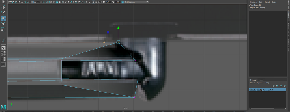
This image (1858 Conversion) is my reference to drawing to create the wireframes, primitives for this gun when I start modelling. This would be the topology process for the revolver.
Here are a few images from the progress I had done over the span of a lesson and a third.


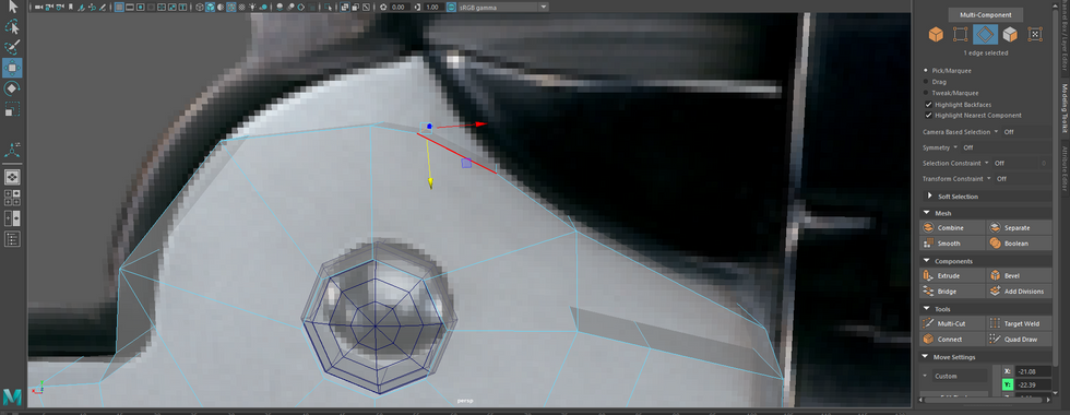
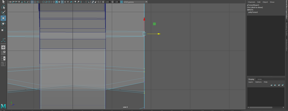
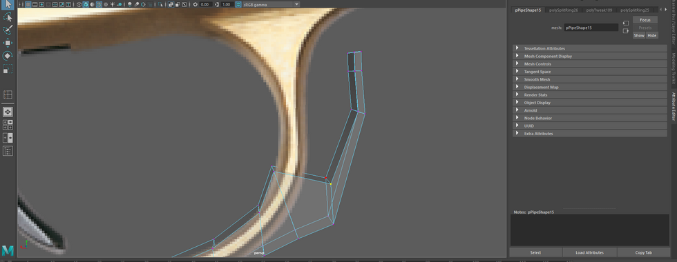
I proceeded and started modelling my revolver. I had some assistance from Sam helping me out with the revolver modelling. The first thing I started off with was the pipe, this pipe would have a sphere added inside of it and I wanted the sphere to be semi-sphere and turned into a pin.
I would bring the inside edges and vertices of the pipe toward the sphere. Now considering the original image for the 1858 conversion image is a transparent image, the image will fit in perfectly into Maya. If you're referencing, always make sure to have transparent images to use when creating your 3D image.
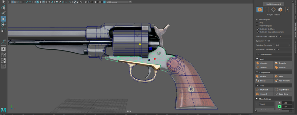
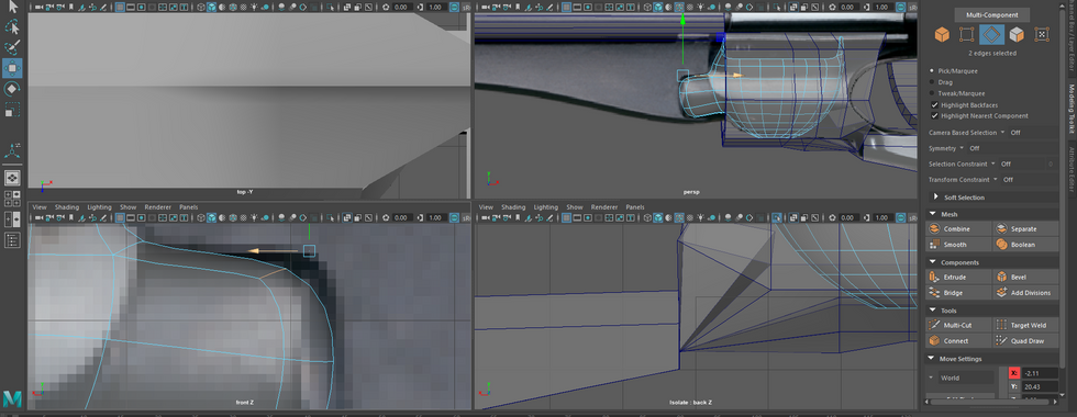
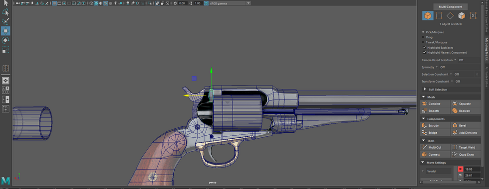
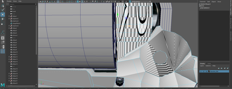
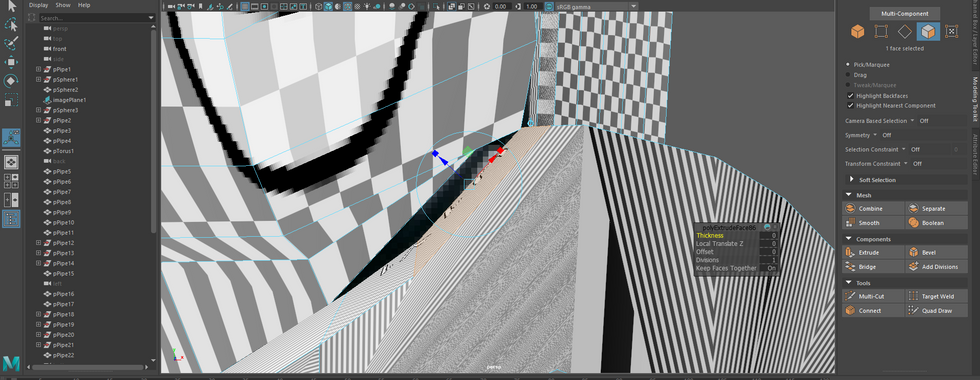
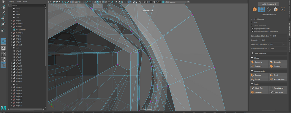
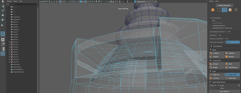
These screengrabs taken from Maya shows the progress I've put into modelling the revolver.
Now keep in mind there are a lot of images for this blog as I took as many screengrabs as I could (probably too many screengrabs in fact). Involving trial and errors,


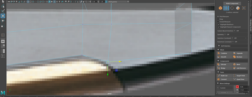
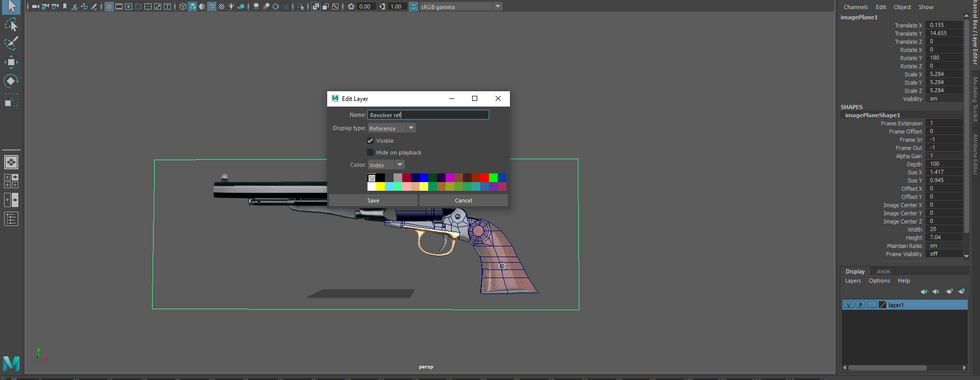
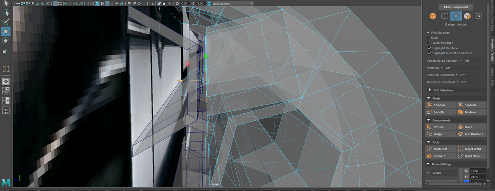
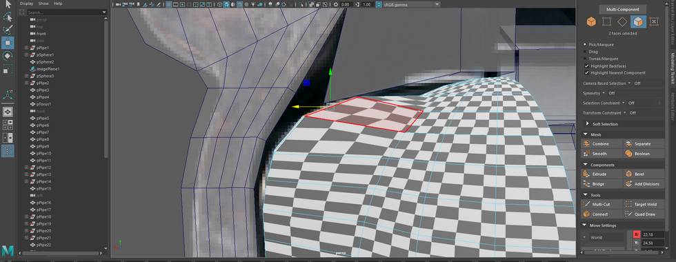
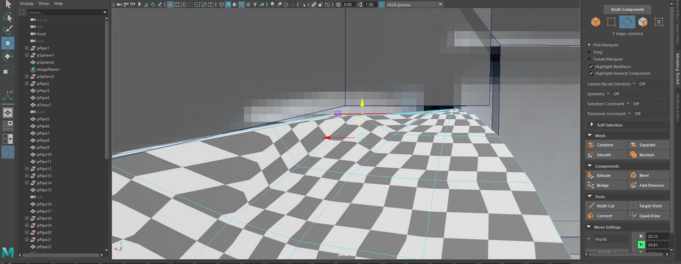
Having extruded out the edges from the shape of my topology, I made the 'revolver' source image layer visible to show where I'm at so far. Personally speaking, I am separating all the shapes out rather than making it into one whole thing. I added 2 more screws which meet the reference I duplicate my original pin. Once the screws were put into place for the revolver, I started working on the frame part of the revolver. I extruded edges, placed vertices appropriately and filled a hole inside the frame.


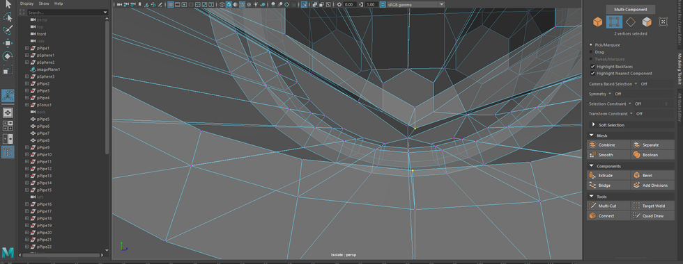
More progress on the frame body of the revolver.


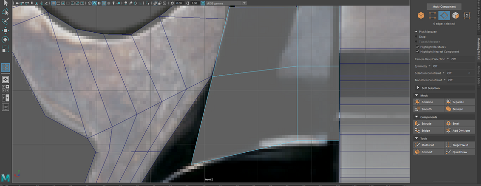
The frame part was finished (for now at least) I moved onto creating the grip handle.


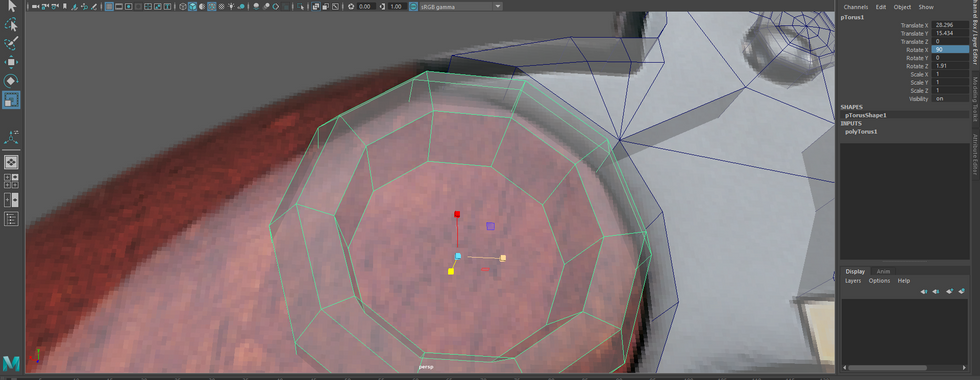
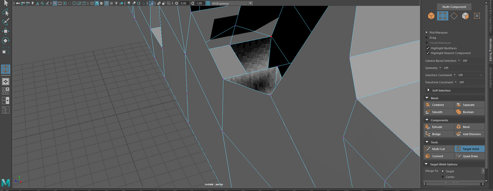
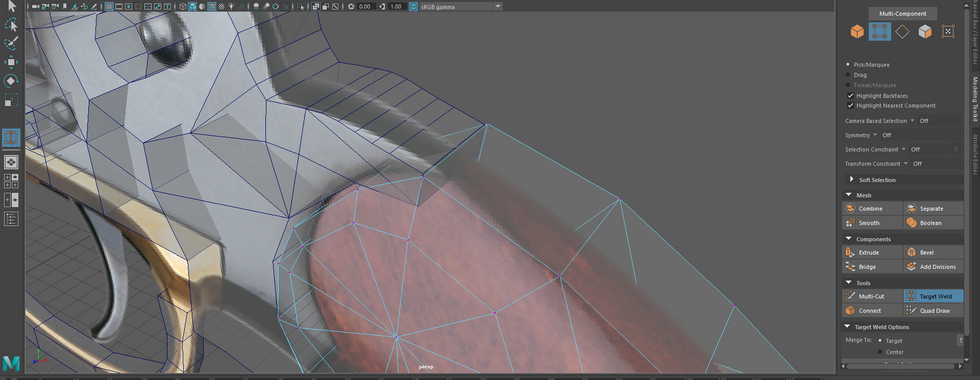
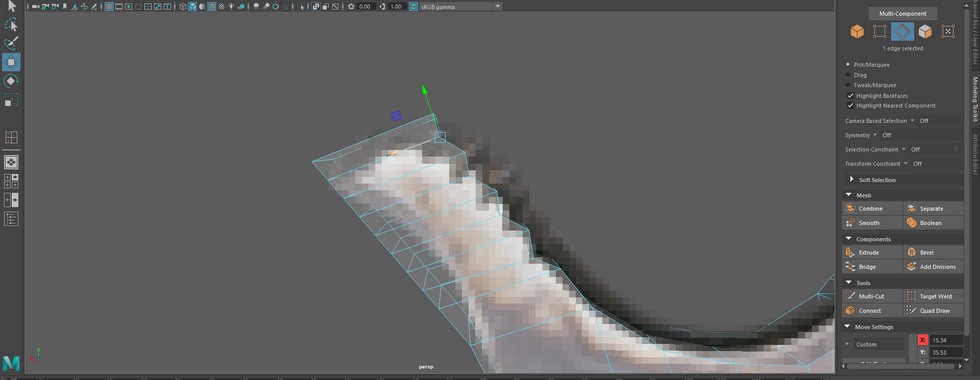
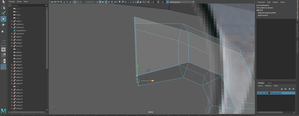
The grip handle, I used the polygon torus shape, changed subdivisions and size, rotated the shape to a degree where the frame faces would meet with the top part of the grip, changed the vertices to make the grip flatter and start extruding the faces and edges to extend the grip. When I extruded I used the edge loop tool. With the edge loops, those edges would extend to the other end of the grip.


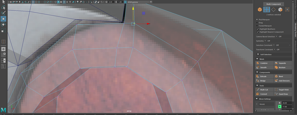
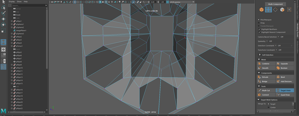
Once I the edges were extended and filled most of the main body of the revolver, I changed the vertices around and did targeting welding. Despite this I faced an issue where the polygons had 3 edges instead of 4. Which ideally each piece of geometry of the face should more than 4 edges rather than less than 4 edges of a face.


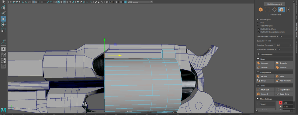
(Warning) A massive amount of images on this particular series of images. This involved a lot of process and trial and error (to some extent) for the magazine, pipes of the revolver.
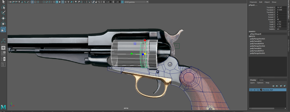
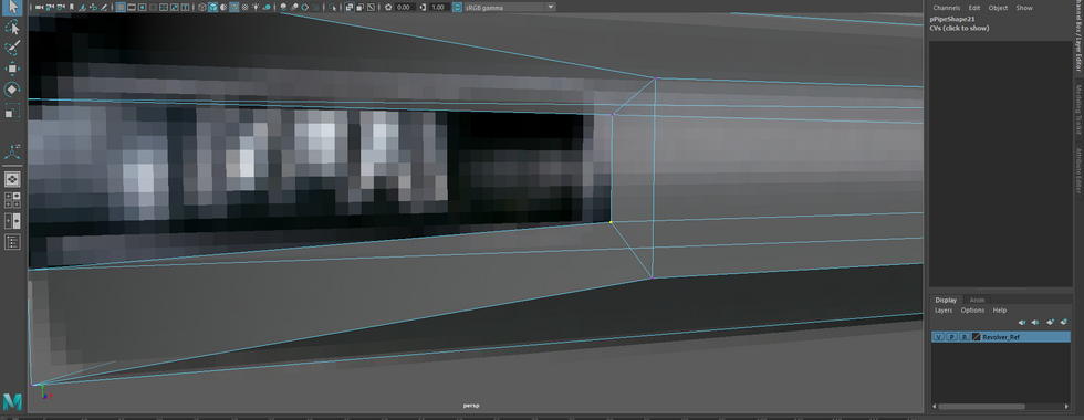
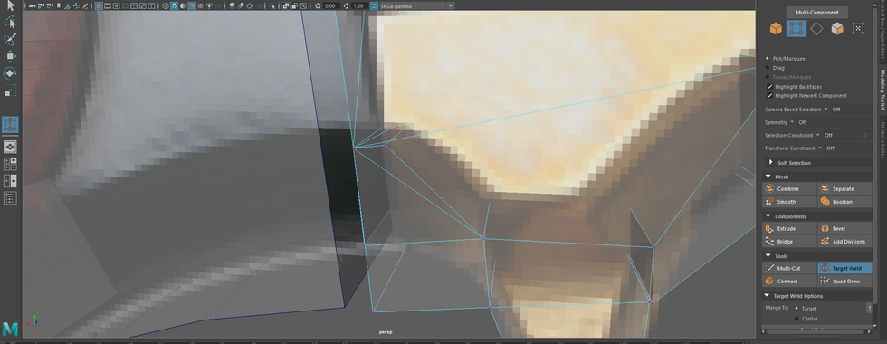
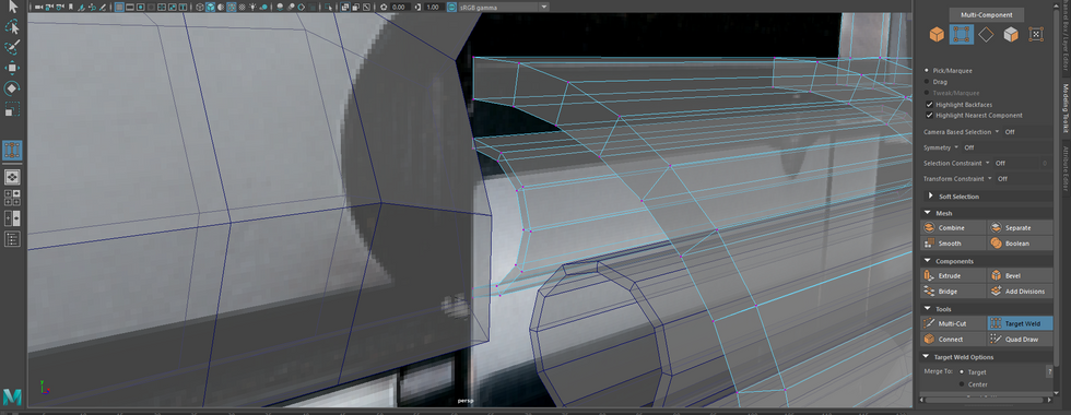
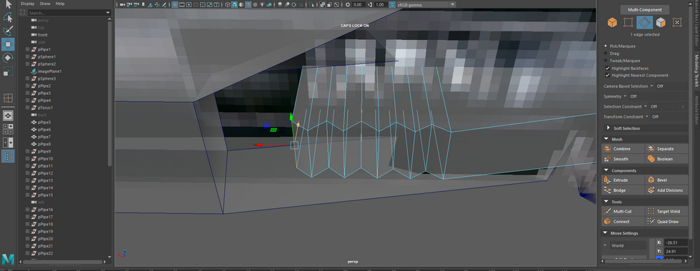
I finished off the grip, then moved onto creating the chamber part of the revolver. I used the pipe shape to replicate the shape of the chamber (which is the storage area of the bullets.). I extended the height and then created more pipes to complete the chamber model. The first cylinder I adapted the edges by changing the top edge by lowering it down. On the end of the chamber (which meets the cylinder release), I filled holes for the pipe. An alternative to fixing is to merge all the veritces to the center.
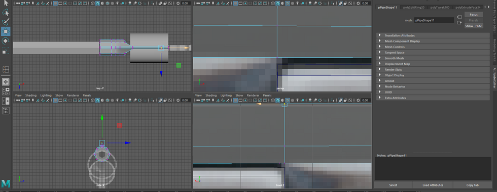
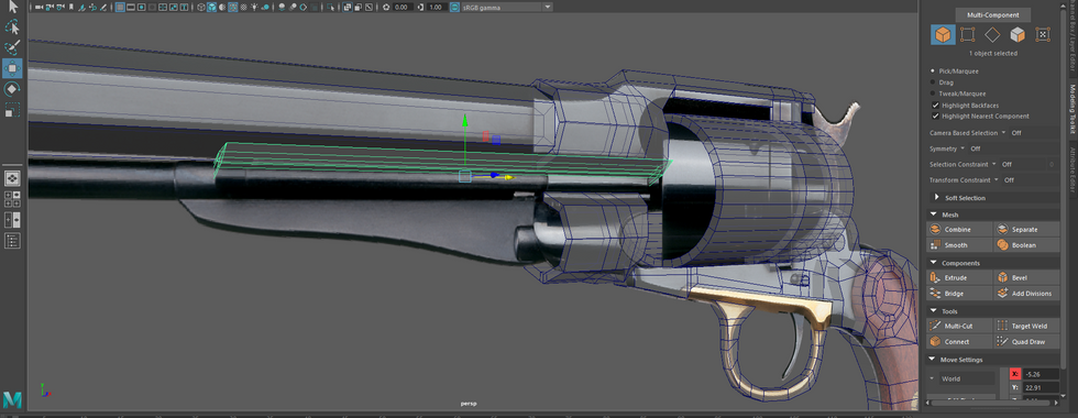
I moved onto the barrel part of the revolver the starting shape I used for the barrel was pipe, extended the height, then worked on the muzzle by using pipes. From there I created an edge loop close to the back part of the muzzle of the front pipe. Once that was done I went back to the barrel area though I worked on the top strap and crane of the revolver. This would be met with extrusions, extensions. There were trial and error involved in the chamber of the pistol.


This part would involve the trigger, trigger ring and extruding parts of the main body of the revolver. I started to work on the trigger and trigger guard parts. I deleted faces, extruded edges, vertices and faces of the trigger guard part. I had only worked on the trigger guard however it was in good shape for the time being which I would go back and actually work on the trigger part of the revolver.


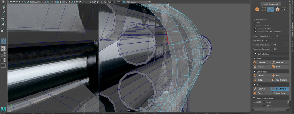
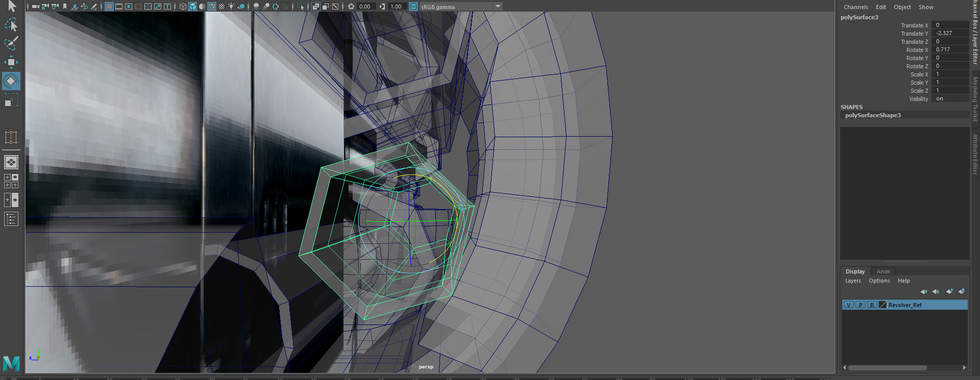
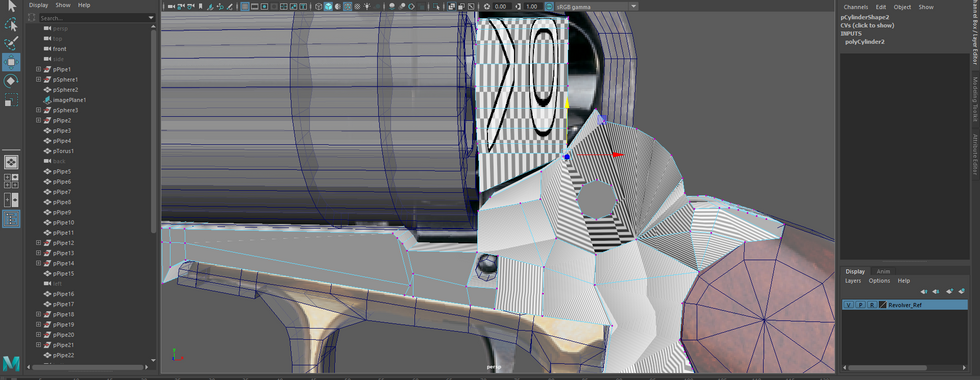
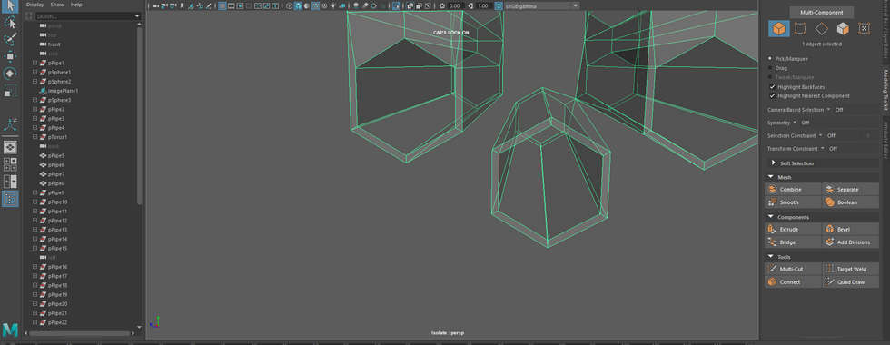
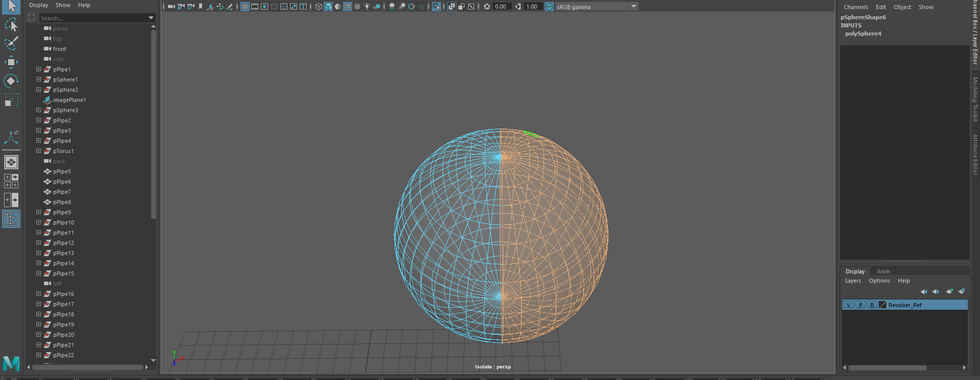
Started working on the cylinder part of the revolver and from there, I changed heights and added multiple copies of the pipes themselves. That being said, their subdivisions remained the same until I got to the front piece of the revolver. I believe it is called a puller. As for the chamber I wanted all the lines on the inside and outside to look perfectly straight. The reason why I want straight lines is for the UV process later on.


Afterwards, I created a sphere shape. I deleted the faces on the top, then moved the vertices and edges to make sure the sphere is inside the chamber. As I pushed the vertices inside the chamber, I pushed some faces towards the front.


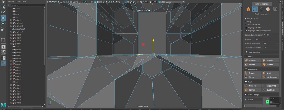
Once the chamber was done, I went back to the main body of the revolver and played around the edges and vertices. From deleting vertices to adding edge loops.


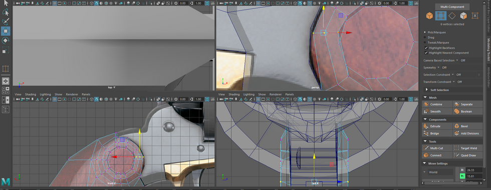


Going back to the trigger area of the revolver, I moved the vertices to widen the trigger.


And that concludes (most of) the modelling process. If you want to read more of the process click the next part of the process for this link below:


Comments