Match movements in Camera and VFX
- Cade.M
- Jun 2, 2019
- 7 min read

Updated: Sep 6, 2019
For Sam's double lesson we discovered a new software called Nuke. The software we use was NukeX. So what is Nuke? Nuke is a VFX software the matches movement, tracking and add CGI from the camera. People use reel shoots to produce the match movements and camera tracking in real time. Or should I say reel time? (pun definitely intended)
Anyways with that out of the way I opened up NukeX. Watched Sam's tutorial videos and then I followed from there. What I do in order to work and follow the video is to multitask just due to tight time schedules and work overloads. I downloaded the first video 5 videos.
Here's the videos I downloaded from Weblearn:

I watched video 1 and I will say it was really straight forward to follow. I personally had no issues or grudges against it. The second video was linear but rather confusing at times, I had problems such as a half 2D image took over 1/2 of the 3D viewer.
So what I did was I saved a (blank) new comp. The file mapping was rather different and odd for what it was but I followed through and placed in an appropriate folder. Afterwards, I grabbed all the files I downloaded from Weblearn. I placed the video files onto the Node Graph (via bottom half of NukeX) and changed the drop box from Global to Input. Then reviewed the video to see how many frames I had. It had x frames. After that I dragged the 24mm lens video to viewer. Not the dragging to overlap it what I mean is to use an arrow and drag the arrow to "Viewer 1". I hit tab on the keyboard and typed in "Lens Distortion" for the video. Then I implemented the keyframes and added one more. Now I hit "detect" on the analysis and then solved after it's detected the grid itself. This was where the video started to show orange points and grid sqaures. After detecting the grid turns from orange to green. Then on the output settings (located in the bottom right of lens distortion) I changed the mode from STMap to Undistort. This makes the lines all nice and straight. Afterwards I had to undistort the live video itself. So I attached the LensDistortion label onto the video itself and applied the same as I did the lens test video.
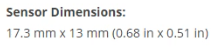
I created another label called 'CameraTracker' this will pick up edges of the objects and dirt within the video. This will configure how the camera is moving. I previewed my settings and turned on preview features to find the patterns and played the video. Before tracking, you'd need to set up a virtual camera in order to match with the real camera. I changed the camera motion to Free Camera. We left Lens Distortion as its already been corrected. The Focal Known is changed to known and depending on the camera's Focal Length. Double it to x number of the focal length of the camera. In my case however, it was filmed on a 24 FL meaning it's 48. If you want to find out more about a camera's focal length and specs. You can find out more on this link. The Sensor Dimensions is the one you'd need to find out:
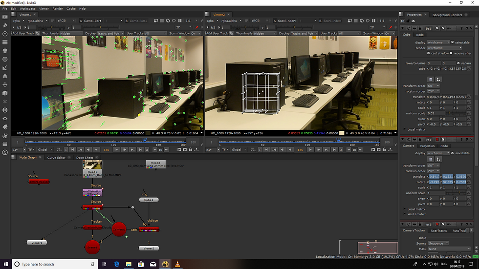
Once tracking process is completed the video will be tracked through. If you noticed that the FPS on the bottom left of the viewer tab is in red; this will tell you it isn't playing back at real time. We'll solve the track from CameraTracker. The orange points will turn to green. In the error part if it's a value of 1 or under it is a good solve but if it's higher than 1 than chances are it's a weak solve. If you had to do so got AutoTracks and find the errors. If you look at the video you can hover over the green points and they tell you what the error number is.
With that out of the way we hit tab on the keyboard on the viewer and it'll enter into 3D.
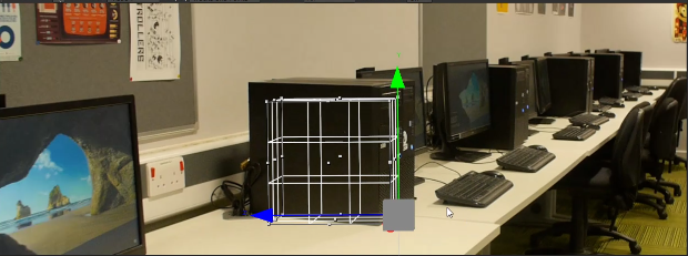
The preferences we're already set up in the process. Meaning that the controls would follow through. Since I was in 3D view I could hover and view in different angles and areas. The points in the 3D viewer compliment each other in 2d space. Meaning it correlates into the 2d viewer and therefore accurate. If you ever notice the points under the grid from the ground chances are it's going to cause problems and making 3D objects out of shape or complex for the matter. If the points can be shifted around it makes the set fitting much easier. I previewed my footage and hasn't picked up many points from the ground meaning this is unreliable. From there I clicked and dragged on the green markers on the carpet area. And set the points as ground planes. So I right clicked and set to selected. The markers will occur as purple. This has changed the the points in the 3D viewer. The next thing I had to do is is to check the accurate solving and using a match movement process. I had to make a geometry shape. So I clicked on one of the corners of the PC tower. Why I did this is because we're creating a PC tower. I left clicked on the green point and then right clicked by doing create > cube and was added into the node graph. Afterwards I created a ScanlineRender in the node graph and directed the cube box to ScanlineRender. We needed to generate a 3D camera so I had to produce a couple nodes. I clicked onto CameraTracker and exported a scene by creating. Now this created a couple of nodes such as 'camera', 'scene 1' and 'CameraTrackerPointCloud'. I tagged the ScanlineRender to CameraTracker. After words the arrows on the node graph looked untidy so I pressed CTRL and dragged the shoulder connectors appropriately. Once all of that was done I added a viewer from the scanline render. Now the viewer was blank so I had to toggle the cube and it would occur on the screen. The cube was very huge so I changed the cube's settings to : x: -0.5 y: -0.5 z: -0.5 and I changed the uniform scale to an appropriate level for the cube. I resized my cube to an appropiate size in order to meet the same size as the PC tower would be. display: wireframe and render: wireframe and then switched back to viewer1. Going back to the selected viewer. I reduced the cubes size to rows: 3 and columns: 3 and then pivoted the bottom corner of the cube (via 2d viewer) Once the cube was placed to the best position and to get it to the yellow cube (the marked point from 2d view) I had to observe the cube in different angles. To some terms the cube's placement wasn't entirely appropriately placed so I did some tweaks in 3D viewer. When I was watching the video Sam suggested to split the viewer tabs in 2. One for 2D and the other for 3D. That way we could operate to see what was occuring and what was going within the 2 viewer tabs.
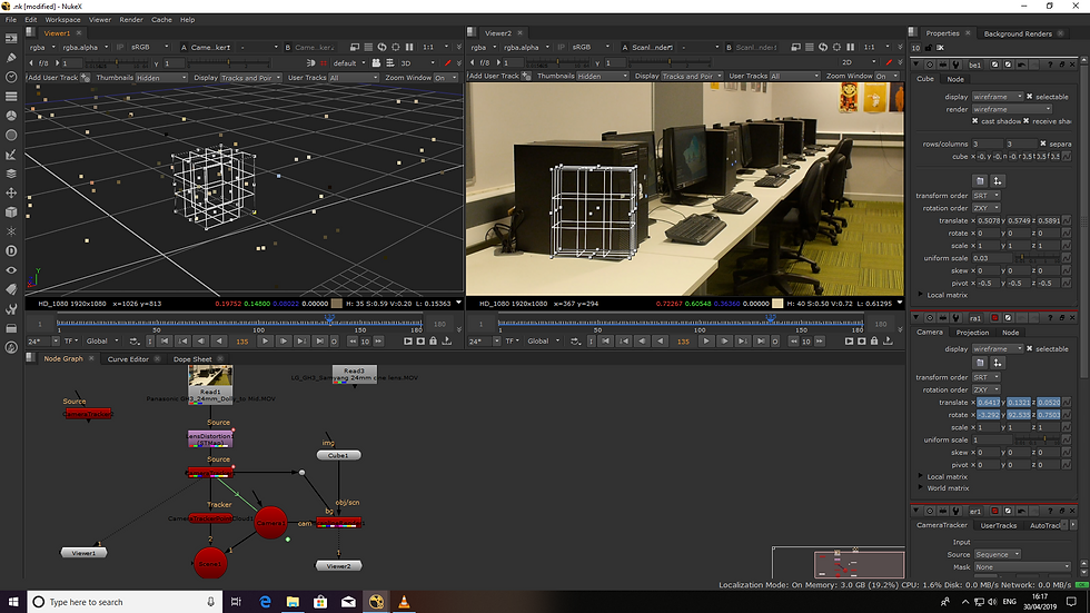
Next thing I did was to rotate, scale and place the cube next to the PC tower and placed onto the table appropriately. This was very finnicky and tweaky to play around with. One thing you could do to play around with is rotate. This helped me out and I checked the cube in 3d perspectives in different views.
Top down (aka eagle view) and side views is what I used to view the cube. After previewing the match movement cube and tracker points in Nuke. I started to export the videos. How I went about exporting the video was I rendered the video. Before I did that however, I checked to see if I had all the node graphs prepared for the video itself. I added the "write" node from ScanlineRender1 to Viewer2. In the write tab I clicked onto the file icon and saved it under the render folder. It's very important to tell the Nuke the folder's name. .mov is what we all used as a video file. Under file type is mov. Codec is: Apple ProRes 4444 because of comping we kept to that codec. The video settings are: 25 FPS. I hit 's' on the keyboard for Project Settings and fullsize format has to be: HD_1080. Once satisfied with the video, hit render.

Now that the video has been created I proceeded to create the geometry for the video.
In this phase, we all wrote the geometry on Nuke. On Scene 1, hit tab and typed "WriteGeo" I doubled clicked on the writegeo once created and placed in the appropriate folder destination. In addition, I created a folder called "GEO export". I also called the file "GEO export and the file type is .fbx. This way it will pick up the FBX file type. Afterwards I executed the file. Now this asked me for the frame range. In my case it was 1-220. So I checked all of my frames to input. After that I went back to execute and clicked OK. Then it ran through the sequence. Moving on to the next part of exporting, Once the Geometry export was done, I exported the camera plates and distorted camera plates. To do this, I clicked onto the LensDistortion node. And hit tab, I typed in "write2" and selected the apporpiate folder destiniation into renders. and named my file "Undistored Camera Plate" and file type is: .mov I made sure the video itself had the same settings for the video such as FPS and resolution. Afterwards, I changed the input from gglobal to input and it'll update the video. From there I made sure everything was OK before rendering and clicked OK in render. At this stage, all of the exporting, geometrizing and rendering was done. And I had finished all of my work in Nuke. Overall the process to render, export and edit the video in nuke was linear and easy thanks to the videos. Thanks to this I now know the process to add VFX, render and export the videos from Nuke. Maya VFX Match Movements: (insert URL here). That blog will entail and progress from this blog,


Comments